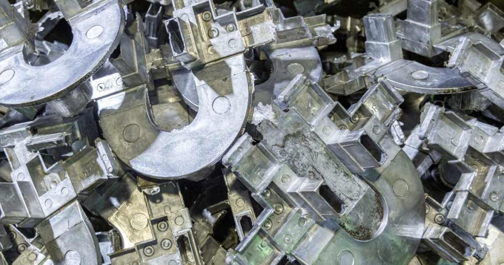
It is important to establish a fully optimized part design before any tools are manufactured for your die-cast product. This can be achieved by applying Design for Manufacture (DFM) best practices. You should also incorporate the use of tools such as Design for Quality (DFQ), Design to Cost (DTC) during the product design stage.
In the following article, our senior engineer Paul Adams shares the key points you need to consider while designing your die-cast parts for manufacturing, and some other important topics you need to be aware of, such as potential defects to look out for.
Design for Manufacture (DFM) Points We Consider
These are the points we consider when we conduct a DFM on a part designed by a client in order to make improvements:
- DRAFT – Draft is a feature added to the part which allows ejection from the mold. Draft is generally a tapered angle between ¼ degree and 1 degree depending upon the size, material, surface finish and process requirements of the part. Adding draft to part allows for easier casting with improved production yields.
- RADII & FILLETS – When designing your cast part, ensure there are no sharp corners or edges. All inside corners should have a generous fillet, this increases material flow and improves strength. Adding fillets to inside corners also eliminates potential stress points. Outside corners should have a radius as large as possible as this will help with material flow and part strength.
- WALL THICKNESS – The best practice with wall thickness is to be uniform in the design. There is no fixed rule about how thick or thin you can go, the design depends upon your product requirements, however, variation in wall thicknesses creates uneven mold fill and potential turbulent flow in the molten material.
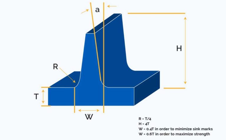
- RIBS – Ribs add strength and rigidity to the part; however, the ribs must be designed correctly. Ensure any ribs added have fillets at the corners to eliminate stress concentration points (as per note in radii & fillets above). Ribs should follow this general design rule:
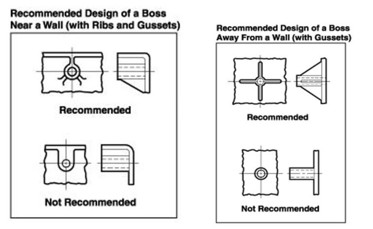
- BOSSES – Bosses are added to castings to provide stand-offs and mounting points. The design of bosses should follow the general rules of casting design, uniform wall thickness, fillets and radii and draft angles. The images below show both incorrect boss designs and the correct boss design:
- WEIGHT REDUCTION – The target is to reduce weight by optimizing the material volume. The more material used in the part design, the longer the die cavity will take to fill, and the cooling time is extended. Both attributes result in an increase in cost per part. One way to reduce material and weight is to include pockets and hollow sections in the design. These can also help with achieving uniform wall thicknesses throughout the part. If you need to increase the strength and rigidity, you can add ribs.
- SHRINKAGE – All metal shrinks during the cooling stage of casting, therefore, the part design needs to have draft applied to the correct surfaces in order to help with the ejection process. The part should always be designed to the desired final dimension as the toolmaker will design the tools to allow for specific material shrinkage.
- PARTING LINES – The parting line is where the two halves of the die separate. This needs to be considered during the design stage of the part. It is always best to discuss options with the toolmaker.
- SURFACE FINISH –
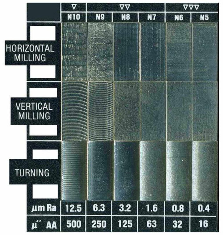
- Post Cast Finishing – This is the surface texture you require on the part surface, which is generally post cast finishing. Now each surface of your part may require different textures, therefore it is important to understand the functionality of your part. You can specify the surface finish using the Ra (Average Roughness) number grade as shown below to get the desired machined surface finish:
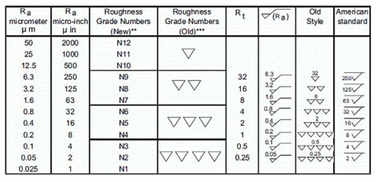
Here is a graph showing the possible finishes:
We look at machined metal surface finishes in more detail in this video from Sofeast:
- ID MARKING – If you require identification marks on your parts, such as date marks, logos, ID marks or other identification marks, you need to ensure they are positioned so they can be changed easily by the toolroom (date of manufacture stamp being a typical mark that needs changing on a regular basis).
- OPTIMIZED MATERIAL FLOW – The use of material flow simulation software is essential these days in the casting design process, it allows you to identify issues with turbulent flow, uneven flow, cavities not filling correctly, and gate optimization. All these points, if not optimized, will result in problematic castings.
- EJECTOR PINS – Ejector pins are responsible for ‘pushing’ the cast part out of the tool. Placement of ejector pins needs to be considered carefully so that the cast part is ejected cleanly without damage as well as avoiding any critical to quality or functional surfaces as ejector pins do leave witness marks and often have a small amount of flash around the pin mark.
About ‘As-Cast Finishing’
For ‘as cast’ surface finishes, this is determined by the surface finish on the tooling. A polished die surface will produce a very good smooth surface finish on the cast part. The North American Die Casting Association (NADCA) has divided ‘as-cast surface finishes’ into five categories (source):
- Class 1: Utility Grade — This class does not have any cosmetic requirement for as-cast finishes and allows for cold shut, rubs, porosity, lubricant build-up and other imperfections. The end-use finish can be as-cast, or the customer can choose a protective coating such as anodize (non-decorative) or chromate (yellow, clear).
- Class 2: Functional Grade — Allows surface imperfections that can be removed by spot polishing or covered by heavy paint. For the final finish, the customer may select decorative coating, such as lacquers, enamels, plating (Al), chemical finish or polished finish.
- Class 3: Commercial Grade — Permits the removal of surface imperfections by methods agreed to by the customer. For the final finish, the design can call for structural parts in high-stress areas. Other options are Plating (Zn), electrostatic painting and transparent paints.
- Class 4: Consumer Grade — This grade has non-objectionable surface imperfections. In the case of rejection because of surface waviness (flatness), as noted by the reflection of light, the customer can determine a course of action in agreement with the die caster. For end use, the designer can use decorative parts.
- Class 5: Superior Grade — The finish that applies to limited areas on the part has a maximum value expressed in micro-inches on the print. The end use consists of O-Ring Seats or Gasket areas.
Die Casting Tolerances
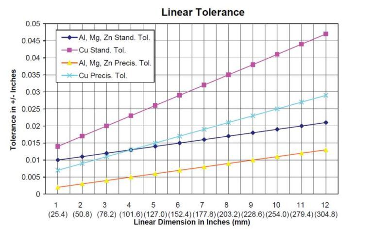
The NADCA has a set of guidelines for die casting tolerances which you should refer to during your part design, however, it is suggested that you do not aim for ‘as tight as possible’ but instead design your parts with tolerances ‘as tight as required’. On sections that are not critical to quality or functionality, set your tolerances as wide as possible, this way, you will achieve higher yield, improved quality and reduced costs.
Here are the tolerances as stated by the NADCA Product Specification Standards for Die Castings / 2009:

Watch this video from where we explore tolerances in more detail:
Most Cast Parts Will Require Post Cast Processing
Post cast processing is much more than just machining the cast part to meet any required dimensions, post-processes can include heat treatment, surface treatment, and vacuum impregnation.
- Heat Treatment – this can improve the casting metallurgical properties such as ductility, rigidity, and abrasion resistance. Some of the heat treatment processing include:
- Quenching – for hardening the casting
- Age hardening – increased strength and reduces ductility
- Annealing – improves formability and machinability
- Normalizing – reduces internal stresses
- Solution heat treatment – This softens the alloy and makes it suitable for further manufacturing applications.
- Stress relieving – minimizes the risk of dimensional deviation during further processing
- Vacuum Impregnation – casts parts may have a porous internal structure which can be a major safety factor in some applications such as aviation and aerospace. This issue is resolved by the process of vacuum impregnation which effectively seals the porosity of metal without having an impact on any other feature of the manufactured part.
- Surface Treatment – techniques offering optimum corrosion protection and create color and gloss effects include anodizing, electroplating or powder coating of metal.
Common Defects in Die Cast Parts
Finally, let’s look at some of the defects and issues you may encounter. A casting defect is an irregularity in the metal casting process that is very undesirable and some major defects can cause castings to be rejected. Here are just three of the more common defects to be avoided:
- Gas Porosity – This is the formation of bubbles within the casting after it has cooled. This occurs because most liquid materials can hold a large amount of dissolved gas, but the solid form of the same material cannot, so the gas forms bubbles within the material as it cools.
- Short Shot or Misrun – A short shot or misrun occurs when the liquid metal does not completely fill the mold cavity, leaving an unfilled portion.
- Cold Shut – Cold shuts occur when two fronts of liquid metal do not fuse properly in the mold cavity, leaving a weak spot.
Hopefully, solid DFM will help you to avoid these defects, but if they start happening during production this is something to take up with the supplier and investigate.
To see a more in-depth explanation of the possible die-casting defects that you may encounter (and should avoid) watch this video:
Conclusion
When manufacturing die-cast products, creating an optimized part design before tooling is made will make the entire process more efficient and result in better quality and lower costs. Using DFM to optimize the design is a good practice, and we went through the various points you need to be aware of when designing earlier on, such as the draft, shrinkage, and the desired surface finish.
You should also be mindful of setting the most suitable tolerances, not always the tightest, and understand that most die-cast products require post cast processing, too.
Lastly, I showed you some of the key defects which you should work with your supplier to avoid or investigate if they begin happening unexpectedly.
*****
Are you manufacturing die-cast products or components? Do you use DFM principles in your design process? How do you find that it benefits you?
Editor’s note: This blog post first appeared on Sofeast.com as What Common Improvements Can DFM Make To Die Cast Parts? and has been edited and reproduced here for Agilian readers.
About Renaud Anjoran
Renaud is a recognised expert in quality, reliability, and supply chain issues and is Agilian's Executive VP. He has decades of experience in electronics, textiles, plastic injection, die casting, eyewear, furniture, oil & gas, and paint. He is also an ASQ-Certified ‘Quality Engineer’, ‘Reliability Engineer’, and ‘Quality Manager’, and a certified ISO 9001, 13485, and 14001 Lead Auditor.


