Electronic product manufacturers use soldering to join electronic components to printed circuit boards (PCBs) by melting a metal alloy (solder) to make a strong, conductive bond. A lot of soldering operations are manual. In that case, soldering jigs are typically used to hold PCBs and components in place, ensuring steady hands and accurate connections!
Getting the soldering right is a must for reliable electronic devices, and a common defect is soldering errors which can cause the device to malfunction or not work at all. However, without the right setup on the production line, precision and stability can be affected. This is where soldering jigs are invaluable for clean, efficient, and consistent results.
What are soldering jigs, and why are they used?
Soldering jigs are specially designed tools that securely hold the PCB and/or components to be soldered in place. When the process is done by hand, using jigs improves both the quality and speed of soldering, reducing the risks of common soldering defects.
Soldering defects you will want to avoid
The use of soldering jigs can solve the following soldering defects:
- Cold Solder Joints: This defect is when the solder doesn’t fully melt or adhere properly to the components, often due to shaky hands. A jig stabilizes the PCB, allowing for the area to be heated and bond properly.
- Solder Bridges: Occur when too much solder creates an unintended connection between adjacent pads or pins, causing shorts. A common cause is when the operator is not skilled at soldering and adds too much solder to a joint to the point excess solder flows and accidentally connects with an adjacent joint or pin.
A jig keeps components correctly aligned, minimizing the risk of accidental bridging. - Misalignment of Components: When components shift during soldering, they can become misaligned with the PCB pads. This is a more common defect when using through-hole technology and smaller components would typically be placed and soldered by an SMT machine, although misalignment can also happen if the operator is not using a jig to help hold everything in place.
- Insufficient Solder: Caused by uneven or interrupted solder application, usually because of operator error. If the PCB is held in place with a jig, it does make the soldering operation easier, however, the amount of solder added is down to the operator in many cases. Some jigs and fixtures automatically feed the correct amount of solder into the correct position and hot solder tips come down and solder the joint making for consistent solder joints (see the automated soldering jig below).
- Excessive Solder: Over-application of solder can lead to blobs that cause shorts or obstruct component functions. A jig helps control the soldering process, preventing over-soldering. Automated soldering jigs and fixtures that auto-feed solder can solve this issue.
- Lifted Pads and Tracks: Excessive movement, heat, or pressure can cause delicate PCB pads or tracks to lift off from the board. A jig minimizes movement, protecting the PCB surface during the soldering operation.
- Solder Splashes: Without stability, the solder can accidentally splash onto other components or areas. A jig reduces accidental movements, minimizing solder splashes and unwanted connections during the operation.
Examples of soldering jigs in action
A jig may be a fairly simple device produced by the factory’s engineers. Let’s look at some examples so you can visualize them in action.
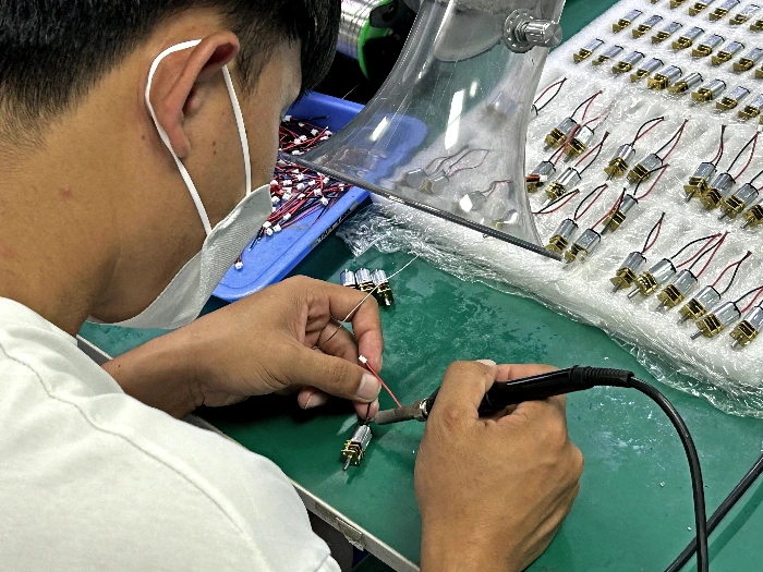
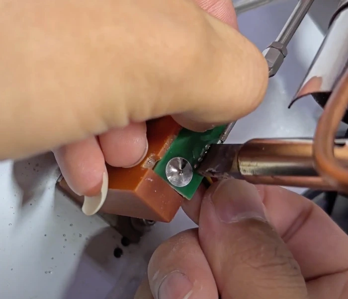
No soldering jig – Level 0
This simply illustrates how an operator would solder straight onto the component or product sitting on the workbench. As you can see, while it gets the job done, it’s possibly unstable and could lead to defects or mistakes if the components move accidentally, for example.
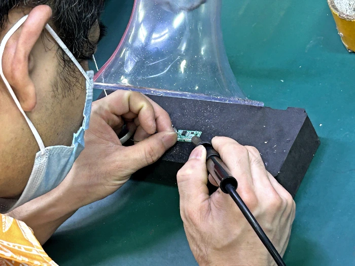
A foam block – Level 0.5
This is still not a custom jig, but a piece of dense foam is utilized to make things a bit more comfortable for the operator, reducing the risk of errors (especially if the board can sit flat, as shown in this photo).
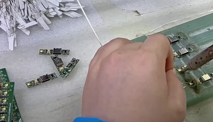
Soldering jig with components placed on it – Level 1
This soldering jig holds the components securely in specifically-shaped channels on its surface allowing the operator to manually solder them in the correct place faster and more easily.
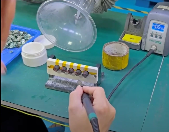
Soldering jig with components placed inside it – Level 1
This is also one of the simpler soldering jigs, because round components are placed inside the round holes to hold them steady for soldering by the operator with fewer mistakes. Placing the components into the jig can be done by the upstream operator, freeing up the soldering operator to focus on his/her core specialty.
Automated soldering jig – Level 2
This machine is an automated soldering jig where the components are held in place by the precisely-shaped jig while the machine lowers down to solder them in exactly the right position. By taking manual soldering out of the equation, risks are reduced.
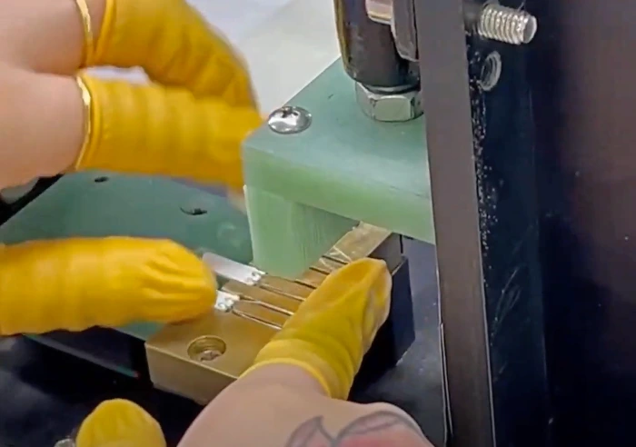
Pre-soldering jig
This jig helps to shape the metal components correctly before the operator solders them in order to reduce the risks of the solder being applied to the wrong area because the metal connector is out of place, for example. This is often overlooked, but in some cases it helps tremendously.
Takeaways
During PCB production, soldering jigs can reduce defects and save time and money over a fully manual operation. That being said, jigs and fixtures can help you reduce risks in many assembly operations, too.
They are inexpensive and effective tools for reducing the risks of defects during soldering operations. As you can see, our engineers made these jigs from plastic blocks, tailoring them so the components had a snug fit and were held stable.
For even more on soldering defects with a focus on PCBs, watch this video:


